GETting past hype
on Grid Enhancing Technologies
There has been a lot of discussion of Grid Enhancing Technologies (GETs) recently as a way to boost transmission capacity. They even got included in recent a Biden push on clean energy and in FERC’s recent rule-making on generation interconnection.
Unfortunately, GETs are not ‘one weird trick to double transmission capacity’.
In this piece I’ll step through a few of the main GETs that folks talk about, and outline the circumstances under which each is useful. This should give a better sense of where efforts can be focused to maximize positive impacts for the transmission system.
The very short version:
Dynamic line rating: Most useful in regions that see winter peaking and have good winter wind resources; less useful in places like the US southwest.
Advanced conductors: Faster and cheaper than adding a new line, particularly where there is unused capacity in the relevant substations; focus on lines <50 miles long.
Advanced power flow controllers: Really useful in situations where network capacity is limited by a specific bottlenecked line with viable alternative paths; not so useful otherwise.
The benefits of GETs are very real, but their use cases are much narrower and limited than the headlines would suggest. These should not become a distracting panacea; we will still need to do the work of building out transmission and energy storage capacity alongside renewable generation to enable the shift towards a zero-carbon power system.
Why GETs?
Construction of new transmission lines has been sluggish (at best) in recent years, falling to a marked low of just ~138 miles in 20211. At the same time, transmission capacity is a key bottleneck on interconnecting additional renewable generation, and new loads like datacenter and electrified heavy industry.
Based on recent analysis by the Lawrence Berkeley National Lab, there are ~1.6 terawatts (TW) of generation and ~1 TW of storage capacity currently in interconnection queues across the country, more than the nameplate capacity of our entire current electric grid. ~95% of this generation is zero carbon, representing an expansion of ~5-10x of our installed renewable generation (if all projects were built).
Grid Enhancing Technologies provide one set of options to expand transmission capacity without the cost and time of new-build transmission, helping to interconnect these vital clean energy resources faster and at lower cost.
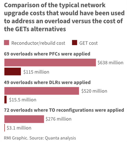
An analysis by RMI and Quanta, focused on the PJM region2 in particular, show the promise here:
But as we’ll see, their applications are narrower than this might suggest, creating the need for a “yes, and” approach to deploying both GETs and new transmission construction.
Dynamic line rating
The pitch:
Increased transmission capacities of up to ~40% for a fraction of the cost (and time) of building out new transmission lines.
How it works:
Many electric transmission lines are thermally limited in operation. As you run current through a given conductor, resistance will create heat causing the line to sag. Too much current and too much sagging creates a risk of dangerous faults3 (and potential damage to the conductor itself).
As a result, transmission lines are ‘rated’ to carry specific maximum quantities of current4 given their expected operating conditions (ambient temperature, wind speeds, solar irradiance, etc.) and allowable sag levels (e.g., before a line would risk hitting something).
The ‘operating condition’ assumptions driving these ratings have historically been static and set at relatively conservative levels (e.g., high temperature, low wind) to ensure safe operations at all times. This means that during most periods the current ratings are too low and don’t accurately reflect how much energy the line could safely carry.
‘Dynamic line rating’ (DLR) seeks to remedy this by adjusting the ratings to more accurately reflect current conditions, allowing grid operators to safely use the extra thermal headroom on cooler and windier days. This can be enabled through granular weather forecasts, as well as field sensors mounted on towers and on the lines themselves.
FERC Order 881 is already driving change here, requiring grid operators to move to ‘Ambient-Adjusted Line Ratings’ that reflect ambient temperatures beginning in July 2025. Many other startups (e.g., LineVision, Heimdall) and grid operators are working on ways to leverage sensors to integrate wind speed, realized line sag, and other variables to more accurately re-rate lines to maximize safe power throughput.
Where it is most useful:
While some version of line re-rating is required by FERC 881, the biggest impacts from this shift will happen in places that have:
Overly conservative static ratings:
Most weather days will not be near the conservative conditions embedded in the prior static ratings. There will (likely) be meaningful upticks in thermal headroom on most days through the deployment of DLR, though this could vary across regions. Impacts will be more muted until planning can be updated to reflect this incremental capacity (see below).
Winter peaking
The capacity of the grid is generally only limited on ‘peak’ load days. In hot regions like California, these all occur in the summer. In colder regions like the US northwest and Canada5, this can happen in the winter. Because DLR is most likely to increase capacity during cold, windy conditions this will be most important for regions that experience winter peaks due to heating load.
Good wind resources in winter months
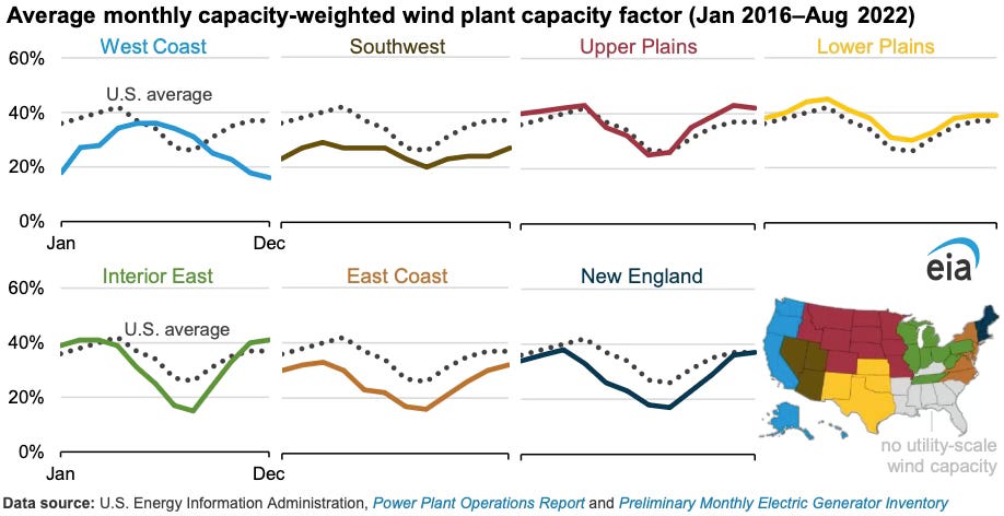
Many regions in the US see their highest wind production during cold, windy months, illustrated in the graphic below. DLR is a good fit for these areas, and over the medium-term could allow them to productively add more wind generation without requiring incremental transmission build-out6.
Limitations on usefulness:
The long-term impact from DLR will likely be constrained by the coincidence of peak days with cold conditions, limited substation capacity, and by the added complexity of modelling dynamic line ratings as part of the capacity planning process.
Coincidence of needs (or not): While it is great for places like Minnesota to be able to squeeze more wind power through a line on a winter peak day, DLR is unlikely to create meaningful extra capacity in summer-peaking regions. In places like California, Arizona, and Texas, transmission capacity will be limited by DLR on exactly the days and times when it will be needed the most.
Non-thermal constraints: Capacity of the system is only as great as the weakest link. In situations where that is the thermal capacity of the conductor itself, DLR will help. In practice, substation equipment7 or power stability8 issues may become the relevant bottleneck, limiting the impact of DLR. This will limit the impact of DLR to lines that are <50ish miles with incremental substation capacity.
Planning complexity: While DLR may unlock incremental capacity in day-ahead transmission scheduling, it is another thing entirely to plan for that capacity 10-20 years out. Significant effort will likely be needed for RTOs and ISOs to figure out how to integrate dynamic line capacity into their study process. While FERC 881 might push this to get solved, in the near-term some may choose to continue to plan against the more conservative operating conditions.
Advanced conductors
The pitch:
Increase the capacity of transmission lines by ~50-100% at a fraction of the cost of building new transmission lines
How it works:
Advanced conductors aim to tackle line sag from a different angle, by improving the conductor itself.
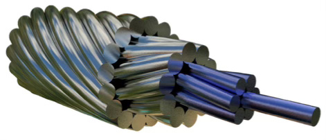
‘Standard’ conductors are Aluminum Conductor Steel-Reinforced (ACSR) and have been in use for a century. These use hardened aluminum wires around a core bundle of galvanized steel, with the aluminum acting as the primary conductor. They are well understood by utilities and their crews, and generally lowest cost.
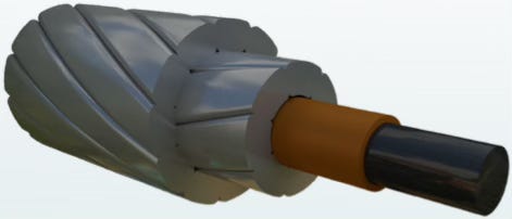
‘Advanced’ conductors aim to improve on this proven design through higher tensile strengths, higher max operating temperatures, and lower resistance (at comparable ACSR operating temperatures). They generally do this through a modified core, with many employing composite cores. The Idaho National Laboratory has a great deep-dive on the specific technology variants here (from December 2023).
The upshot is that these advanced conductors can achieve higher ampacity without violating thermal sag constraints, albeit at a higher cost per mile than ACSR. Operated at the same temperatures as ACSR conductors, many can also achieve higher efficiencies / lower lines losses, reducing energy requirements and cost for customers.
Among other reforms to the generator interconnection process, FERC Order 2023 directed that the interconnection process should include evaluations of alternative transmission technologies like advanced conductors. This means that advanced conductors will be part of the repertoire of solutions that can be used to address constraints on interconnecting new generation. While not directly affecting load interconnections, this move should still boost widespread adoption of advanced conductors.
Where it is most useful:
Reconductoring of existing lines: Advanced conductors are most appealing for re-conductoring of existing transmission lines. For a relatively limited investment (and often simplified permitting, given use of existing rights-of-way), capacity can be boosted by ~50-100%. This is particularly appealing in built-up urban environments where there is limited space for new build construction.
Long-spans: Advanced conductors are also uniquely useful for line segments that cross long spans (e.g., over rivers or highways). Their minimal sag allows for shorter, cheaper transmission towers than would be required with ACSR.
This expectation is borne out by the types of projects that have been happening with advanced conductors, with many looking like9 this reconductoring by Southern California Edison of a ~230kV line with an ACCC (Aluminum Conductor Composite Core) conductor. In that case, the capacity could be expanded using existing towers and rights-of-way, which was particularly important in urban Los Angeles / Orange County.
Limitations on usefulness:
Non-thermal constraints: Similar to DLR, advanced conductors are mostly useful on lines that are thermally constrained via conductor sag (and have incremental substation capacity). This means lines <50ish miles long10. Power stability issues are even more notable as a constraint for advanced conductor usefulness, with many having higher resistance at their max operating temperatures11.
Limited track record of reliability: Utilities are deeply conservative organizations and generally want to see extensive evidence of reliability before broad deployment of new technologies. As the conductor manufacturers keep innovating, each new technology has a new burden of proof to overcome. This is not helped by the new installation procedures required of field crews that—performed improperly—can risk damaging the conductor12.
While #2 here will be overcome with time (and with prodding from FERC), non-thermal constraints are more limiting.
Advanced power flow controls
The pitch:
Avoid costly upgrades to deal with N-1 contingencies, install advanced power flow controllers instead!
How it works:
Most transmission systems are planned against N-1 and N-2 contingency scenarios, representing the loss of 1 and 2 nodes respectively. The lack of a given node (e.g., substation) shifts the grid’s topology and alters the flow of current across the network. This shifting of load can cause thermal overloads in lower capacity parts of the grid.
When these potential overloads surface during the transmission planning process, the traditional (expensive) solution is to bolster the offending line or substation (e.g., through reconductoring or new build construction). Advanced power flow controls (APFCs) provide a lower-cost alternative, using advanced power electronics to shift load away and avoid breaching thermal limits.
Even outside contingency scenarios, limited capacity on specific transmission lines can create congestion between low-cost generation and customer loads. Left unaddressed, capacity limits on congested lines means nearer, higher cost (often hydrocarbon) generation must kick in to fill the gap. One report from GridStrategies put these costs in 2021 at ~$7.7B for regions covered by regional transmission organizations (RTOs) and ~$13.3B across the US as a whole.
There are a number of specific technologies that fit under the ‘advanced power flow controls’ bucket, each working in their own way to manage reactance and impedance on a given transmission line. One prominent example, the SmartValve from Smart Wires, does this by injecting voltage out of phase with a line’s current to either increase its impedance13 (and push power onto alternative lines) or decrease its impedance (and pull power onto the target line).
APFCs are notable because they use modern power electronics to rapidly respond to grid dynamics in real-time, allowing for more fine-grained automated and manual control by grid operators. While Smart Wires originally launched with a conductor-mounted solution, most APFCs today are mounted in substations.
Where it is most useful:
Heavily meshed transmission networks: APFCs are more useful in heavily meshed systems with multiple alternative paths for power to flow (e.g., PJM in the US northeast), rather than systems with fewer alternative branches (e.g., CAISO).
High congestion areas: APFCs are particularly useful in areas with significant congestion, indicating there is value in expanding transmission capacity beyond merely bolstering reliability during contingency scenarios.
Beyond these general principles, there will also be grid-specific scenarios and use cases where shifting the grid topology through APFCs could be the lowest cost solution to a given grid need. APFCs are also addressed in FERC Order 2023, so should be deployed in generation interconnection situations where they make sense.
Limitations on usefulness:
Absolute transmission capacity: APFCs can shift power flow across alternate paths to maximize utilization of all available capacity. But they cannot create new capacity that doesn’t exist. While these are a useful tool in the toolbox to get the most out of our existing network, they are not a substitute for absolute increases of transmission capacity to interconnect incremental load and generation.
Availability of alternate paths: APFCs need alternate paths to shift power flow onto (or from). These won’t always be available, and the opportunity for APFCs may be saturated at a relatively low level. In a 2018 report, EPRI estimated that 13 targeted APFCs would resolve most APFC-addressable congestion within PJM.
Overall, these technologies well help us squeeze more capacity out of our existing transmission grid, with minimal incremental investment relative to new build-out.
But there are meaningful limitations around applicability, added complexity in planning, and full-potential impacts that should give pause to those who think that GETs will provide an easy step change in capacity. In particular, many GETs address thermal overloads in one way or another, but the long-distance lines used to interconnect renewables (particularly in the southwest) are limited by power stability not heat.
GETs are an important tool in the toolbox, but we still need to get to work build out transmission capacity.
PJM originally stood for Pennsylvania-New Jersey-Maryland, though the region now covers Washington DC and all or part of 13 states (Delaware, Illinois, Indiana, Kentucky, Maryland, Michigan, New Jersey, North Carolina, Ohio, Pennsylvania, Tennessee, Virginia, West Virginia).
Generally line-to-ground faults (e.g., if the line sags so much it hits something). Line-to-line (where lines swing in wind and hit each other) are also possible, but often have cheaper remediations.
Grid components are operated at specific target voltages (e.g., 500kV between two transmission substations), only the current should change as power and energy demands change.
Due to their relatively muted air conditioning loads in summer, and relatively high heating loads in winter. The shift from gas and oil-fired heating towards electric heat pumps could accentuate this dynamic in many regions.
This will be most impactful for regions that were using single static line ratings. In practice, some regions already vary these seasonally (i.e. winter and summer) in which case the impact will be more muted.
While many substations may have incremental capacity, they are not (generally) designed to carry meaningfully more current than the lines they connect. Upgrading transformers, duct banks, and or circuit breakers will add to the cost of any of the technology deployments outlined here.
Over long distances, voltage and reactive power management become binding constraints. At low loading, long transmission lines effectively act like capacitors and generate reactive power, potentially causing over-voltage conditions. At heavy loading, the inductance of the line causes it to absorb reactive power, potentially causing a voltage sag. For inter-regional lines, managing these effects dominates the thermal management around conductor sag.
Appendix A of the Idaho National Lab report on Advanced Conductors here has an extensive list of projects across the US that utilized advanced conductors.
Some longer new-build transmission projects have used ACSS (Aluminum Conductor Steel Supported). ACSS sags less than ACSR at equivalent temperatures, but more than ACSS at its max operating temperature (of up to 250 degrees C), requiring taller towers or higher line tensions to take full advantage of the higher ampacity. Therefore, unlike composite-cored advanced conductors, ACSS is more appropriate in new build situations than reconductoring.
This would lead to more extreme swings between capacitance and inductance across load levels, making power stability more challenging.
Composite core conductors in particular often have minimum bend limitations that are wider than with equivalent ACSR conductors. If a crew bends the conductor too much in installation, it could be damaged and more likely to fail. Splicing advanced conductors can also require more complicated procedures (e.g., the use of a powerful press) that are challenging to perform in the field.
Impedance is a function of resistance and reactance for a given line, and represents the opposing force keeping current from flowing through a given line segment.


